
JEE Advanced 2026 Paper 1, Physics Section 4 Q3: Faraday’s Law of Induction
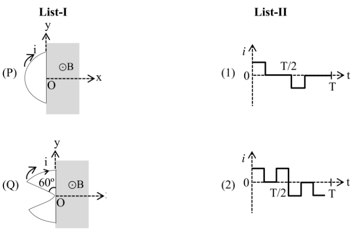
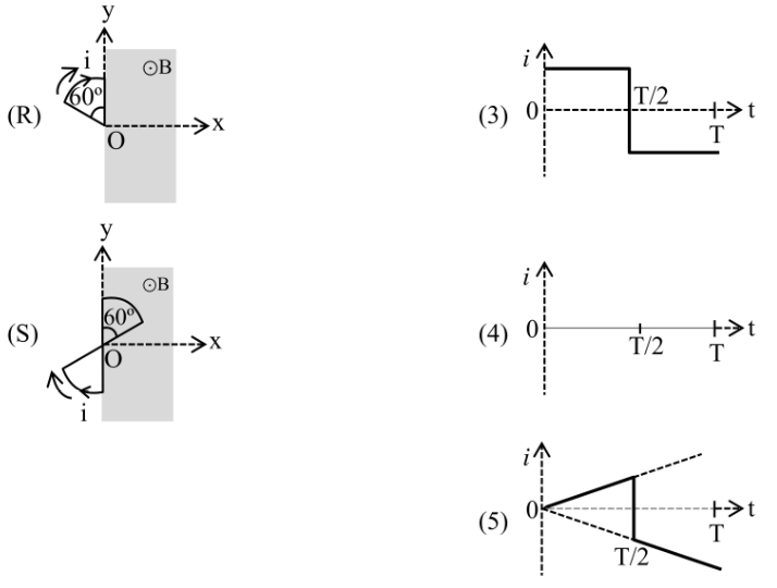
List-I contains four conducting loops lying in the XY plane, as shown in the figures. The loops are rotating about Z axis passing through the point 0 with time period T in clockwise direction. The region contains a uniform magnetic field B in the +z direction. List-II contains the qualitative variation of the induced current for each of these loops. Choose the option which describes the correct match between the entries in List-I to those in List-II.
- A
P 5; Q 4; R 1; S 3
- B
P 3; Q 2; R 5; S 4
- C
P 3; Q 2; R 1; S 4
- D
P 5; Q 1; R 2; S 3
General principle. Induced EMF appears only when the area of the loop inside the field region changes with time. While the loop sweeps through the field with constant entry/exit area, is constant; when it is entirely outside or entirely inside, .
(P) Semicircular loop initially in . Starts at ; as it rotates, area inside field grows at a constant rate (semicircle pivoting about its straight edge), giving a constant non-zero current during one half-period and zero current when fully outside. This matches a single rectangular pulse over T/2 to T: P 3.
(Q) Wedge initially making 60° with the field boundary. The constant-rate entry begins immediately after a small delay ( to align with the field edge) and lasts for a fraction , producing a pulse structure with successive positive and negative pulses as the wedge enters and exits multiple times per cycle: Q 2.
(R) Small triangular loop initially aligned along the field edge. Begins entering at and exits at , giving a single short rectangular pulse during 0–T/2 (with the corresponding return pulse cancelled in this geometry): R 1.
(S) Symmetric two-lobe loop straddling the field edge. Whatever flux enters one lobe leaves the other simultaneously, so the net EMF cancels: throughout. S 4.
Mapping P 3, Q 2, R 1, S 4 corresponds to option (C).
Concept behind this question
Faraday’s Law of InductionNotes, formulas and examples →More previous year questions on Faraday’s Law of Induction
Practice more Physics Section 4
Concept-wise practice with instant solutions on Fundamenthol.
Start practicing →