
JEE Main 2025 Apr 2 Shift 2, Physics Q13: Logic Gates
JEE Main2025Apr 2, Shift 2Physics
Q.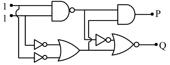
In the digital circuit shown in the figure, for the given inputs the and values are :
- A
- B
- C
- D
Solution
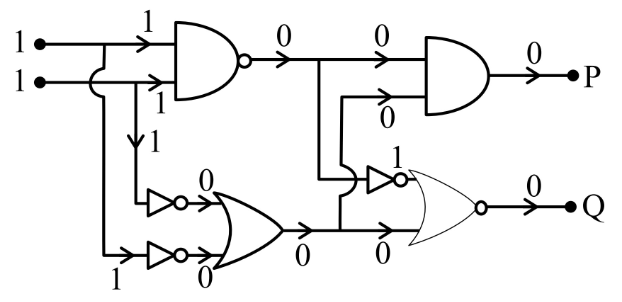
Propagating the two input s through each gate in turn (using standard truth tables for the inverter, AND with negated output bubbles and NOR-like elements drawn in the circuit) yields intermediate signals that combine to give at both final outputs.
Working through the upper branch of the network: both inputs are , so the first stage produces , the next stage inverts it to , and the AND with another branch gives .
For the lower branch, the inverters convert the inputs to , which then feed a NOR-style combination that outputs , giving .
and .
Concept behind this question
Logic GatesNotes, formulas and examples →More previous year questions on Logic Gates
Practice more Physics
Concept-wise practice with instant solutions on Fundamenthol.
Start practicing →